DIY Offgrid Project – Battery Management System and Contactor

This box of stuff will protect the battery in my home brew 23kwh storage system. Given the failure modes for lithium batteries involve dying permanently and catching fire you want to get this right. This will be able to stop the inverters from draining the battery and if things get really outside the comfort zone it will disconnect the battery completely. I could disconnect the solar panels from the inverters if I needed an absolute override for high voltage but I don’t think that’s going to be a problem.

The Batrium BMS is the brains of the operation.

The big thing on the left is the contactor. It’s designed for forklifts. It’s rated at 48 volts 200 amps DC. It came via AliExpress.

The relay coils are also 48 volt DC although the contacts aren’t really rated for that many volts. I’m not expecting problems because the main contactor draws only two hundred milliamps which isn’t going to sustain much of an arc.

If either relay is closed the contactor will close. The BMS has a pair of FET outputs that connect to ground when enabled. One is programmed as Charge OK and the other as Discharge OK. They can also be set to open and close a bistable contactor but thats not what I have and they scare me.

I designed everything using a sketch tool on my ipad called You Doodle.

Then I started to put it together. Here’s the result so far.

Next task is making the aluminium strap between the contactor and the current shunt. Then I’m ready to bolt it all to the wall.

UPDATE

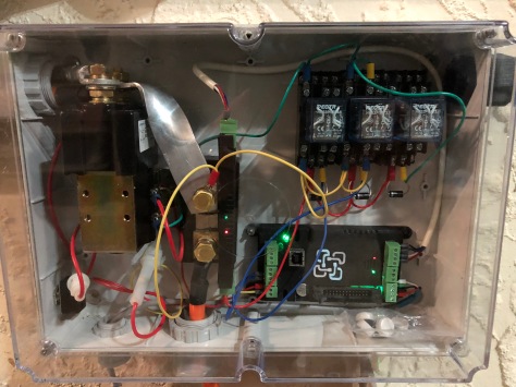
Here it is mounted to the wall:
IMG_1191.jpg

Note the shunt is operating BACKWARDS. There is a setting in the shunt setup window that tells the WatchMon that the shunt is reporting backwards.

After I reassembled everything I got really wildly fluctuating readings in the tool.

Pulling everything apart I discovered that one of the two brass screws that hold the sensor to the shunt and carry the voltage from the shunt to the sensor was loose. I probably put too much force on the sensor when wrangling everything into place.

One day I may replace that awful ugly aluminium bar. I went to the trouble of twisting it so you can see the LEDs but then I discovered that they are visible through the side of the sensor too! Sadly twisting it made it less than pretty.

Another interesting observation is that the contactor runs very hot. I know the EV community have used various circuits to reduce the average hold current on the contactor but it’s probably easier to put a little fan in the side of the box.

DIY Offgrid Project – Monitoring

If you are a fan of solar power you have probably heard of pvoutput.org, a cloud service that records and graphs the generation and consumption of member’s renewable energy systems.

The new system is graphed here. If you hunt around you can find my existing grid-tied system too. As of writing, with 3kw of panels and running the pool pump and garden lights, a day looks like this:

IMG_1111.jpg

Power is measured in watts “w”. Energy is power over time and the unit often used for electricity is kilowatt hours “kwh”, which is 1,000 watts for 1 hour. It’s also 2,000 for half an hour or 500 watts for 2 hours.

The dark green line is the power out of the solar panels that is charging the battery and running the inverter loads. The red line is the power consumed by loads and the overhead of the inverter itself which is around 50 watts, around 1.2kwh per day. The large green area above the pink “energy used” is the effective energy overheads of the system and losses while the charger tries to “balance” the battery pack. At present I appear to be wasting about 4kwh per day which is quite high when you stop and think about the maximum 20kwh per day the solar panels can produce. That said, my methodology is a little primitive.

The PIP inverter has an RS232 serial port which is “normal” for IT 20 years ago but unusual for solar kit these days where RS485, MODBUS or CAN are much more common. You need to talk at 2400 bits per second, 8 data bits, no parity and 1 stop bit. The protocol has been documented and I found some Python code to talk to the inverter in the AEVA PIP forum but it is for loading data into a database.

Data available includes the voltage and amps from the solar panels, the battery voltage and charge current in integer amps and the voltage and watts being supplied by the inverter to loads.

I cleaned up the existing code that reads the data about once every 1.5 seconds and wrote some that does some maths and logic and then uploads the data to pvoutput every five minutes. You can find my code stashed away on that forum.

I multiply PV volts by amps to get watts which is legitimate for direct current.

I multiply that by the duration in hours since the last sample (about 1.5 seconds but measured to microsecond accuracy by the RasberryPi) to give watthours.

I do the same for the inverter load which is reported in watts (and also in volt amps which is probably a source of discrepancy for those of you who understand reactive loads).

All of this is summed and then uploaded on the first sample after the wall clock minutes are integer divisible by 5. (Remember modulo?)

The next extension to the code is to listen to the Batrium BMS and upload the StateOfCharge% and net current in or out of the battery from it. It’s much more accurate than the integer amps from the PIP inverter.

DIY Offgrid Project – Integration Part 2

Lithium Iron Phosphate batteries like all lithium batteries need a battery management system to protect the individual cells from being over charged or over discharged.

This is a Batrium M8 Cellmon.

It connects to a monitoring box that has an embedded computer. In turn there is some software that only runs on a Windows machine that visualises the performance of the battery.

If a cell reaches maximum safe voltage before the others have fully charged the pack will not be fully charged. The red bits are the cellmons that are “by-passing” which means they are attempting to limit the voltage across their cell in an attempt to “balance” the voltages across all the cells. They can do this for about 1 amp which means it will take a while before the battery pack is fully “top balanced”. I can help this process along by discharging a high cell with a load like an incandescent headlight bulb. But during the main part of the charge and discharge cycle the cells are all at much the same voltage so the real imbalance is relatively small.

DIY Offgrid Project – MC4 Fuses

Solar PV panels are wired in series to get to the desired voltage and then these “strings” are connected in parallel to deliver the required current. Each string is supposed to have a fuse in series to protect against excessive current flowing through the string. Solar panels have several characteristics including an open circuit voltage (Voc) and a short circuit current (Isc) Isc which is typically the maximum current the panel and hence string can produce. Deployment rules require a protective fuse in series. The panels I’m using say the fuse should be no more than 15 amps. My panels can’t produce more than 10 amps so the output of the panel isn’t going to blow the fuse.

What is the fuse protecting? It’s protecting the panels from being damaged by being back-fed from several other strings and also from damage your inverter fails and drives a high current back through the panel. It is also protecting the cabling from excessive current although I’m using 4mm² cable which is rated to carry 25 amps. You have to try hard to imagine the failure scenarios on a low voltage system like mine that would cause the fuse to blow. Never the less, I have one of these fuses in series with each string of three panels.

Having wired three strings of three panels, with fuses in-line, I short-circuited them to test performance.

Nearly 20 amps Isc – short circuit current. Not bad for late in the day!

And a word of warning. These were advertised as “fuse diodes” but there is nothing “diode” about them so don’t pay a premium for that.

DIY Offgrid Project – Integration Part 1

I have been busy over the last few weekends and the weather has been unappealing for climbing around the roof when I have had time so I still don’t have an solar panels installed but all the parts of this system have been cluttering up the house so I decided to mount things on the wall and test out strapping the battery cells together this afternoon.

The straps came in a set of four at Bunnings and the timber end plates are some leftover Ikea solid timber bench. The best advice for LiFePO4 cells is that they should be strapped together because the cells bulge when they are full charged due to the lithium ions that are deposited within the graphite coating of the cathode during charging.

The two solar isolators are overly optimistic Chinese switches that claim they are rated at 32 amps. I’m doing 10 amps per contact so we should be good. The DC breaker is rated for 600 volts DC and 125 amps which is the absolute maximum the inverter is rated for. I hope I can find another enclosure the same for my second inverter. I bought this one when I made the 20 amp Tesla charging adaptor. IMG_0936

The cells will be tied together with these intercell links. They are 25mm by 3mm so they have a 75mm² cross section. That’s equivalent to 50mm² of coper which can handle around 150 amps with a recommended breaker of 125 amps. That’s around the maximum continuous rating of the cells anyway.

IMG_0917

The white tube on top of the cells is Alvania electrical junction grease designed for aluminium connections. You can buy it here. This will all make sense when I join everything up and integrate the Battery Management System.

DIY Offgrid Project – PV panels

I found 13 x 250 watt PV panels on Gumtree for $100 each. It turned out they came with mounting rails and most of the clamps. That’s about $500 of cost avoided! The panels all appear in perfect condition. That’s 3,250 watts of panels for 40 cents per watt. By the time I get them on the roof they will owe me nearly 60 cents per watt. That’s about 4 cents per kWh over ten years. Cheap power!

IMG_0833

The open circuit voltage of the panel, Voc is 37.6 so three in series is 113 volts which is less than 120.

There is an interesting loophole in the electrical safety rules. You don’t need to be a licensed electrician to install DC equipment that operates below 120 volts. Technically you don’t have to follow all the pesky safety rules around isolators, conduits, fuses and earthing. You know, all the SAFETY rules. I will be following those rules regardless. (You can find the rules online if your Google-foo is good. I don’t want to draw attention to them because hiding Standards behind paywalls is what we do in Australia: put up a fence and charge rent and if I link to the set I found they will probably be taken down.

More to come! Installing and wiring the panels is next.

DIY Offgrid Project – goals

The goals of my home brew off-grid solar storage system are:

  • make my house relatively black-out proof – keep the lights, fridge, hot water and internet running
  • run big daytime loads direct from solar – the pool, the air-con
  • reduce my effective electricity cost to $0.10 per kWh assuming a 10 year life of the system
  • cover the capital expense with two years of savings

I need to generate around 1 megawatthour of electricity each month to do this.

Based on the performance of my current system, in summer I need 5 kilowatts of solar panels, but in winter I need significantly more, around 10 kilowatts.

I have 3 kilowatts on a 2.8 kW grid-tie inverter already and I want that to export like crazy to maximise my return.

A key reason for building an off-grid solar system is to avoid losing my feed-in tariff. That’s going to take some dancing at some point after SAPN look at the NearMap photos and notice I have a bunch of new solar panels.

In the short term I need around 6 kilowatts of extra panels to generate all the electricity my household consumes.

Of course I will need to focus consumption into daylight hours as much as possible because that’s easier than storing it. My largest nighttime consumer is the pool but I can just change the timer. If I have a surplus and my car is home I will charge it. That will be a whole other project 🙂


DIY Offgrid Project – Batteries

A couple of years ago I bought a Tesla and put vanity plates on it that say OFFGRID.

Ever since then I have been trying to make the dollars make sense to install some batteries, an inverter and a bunch of solar panels in an attempt to charge my Tesla and keep my pool clean with free solar electricity.

About five readers are about to leave a comment that I don’t need a battery to achieve that and indeed I don’t but why have a simple life when I can add technology?

Recently some associates found a stash of 460 AmpHour Lithium Iron Phosphate storage cells being disposed of and I managed to get 16 which means I now have a 52 volt, 460 Ah, 23kwh battery. You can cycle these cells to 80% discharge thousands of times. If you keep them between 20% and 80% State of Charge (SoC) they should last much longer. 60% of 23kwh is still 14kwh which is more than my overnight electricity consumption.

It seemed appropriate to put the batteries in the boot of my Tesla.

LiFePo4 cells are great technology. They don’t need water and don’t produce hydrogen gas. If you over charge them or allow the terminal voltage to exceed 4.2 volts you will damage the battery and the classic failure mode is to catch fire. If you over discharge the cell, to below 2.8 volts you will damage the battery and the classic failure mode is to catch fire. I’m obviously going to need some sort of battery protection or management system.

Before the project is finished I’m also going to need solar panels, mounting frames, isolating switches, fuses, circuit breakers, an inverter and some sort of overall monitoring and control system.

I’m going to try to do as much of it myself as I can but there are some parts which will need an electrician.

Welcome to my solar storage adventure!

Correlation implies causation?

Let me start by warning that this isn’t investment advice.

I found an interesting graph at the end of a Finder.com.au article on mobile performance showing the falling cost per gigabyte of mobile data on what they described as flagship plans. I take that to mean approximately $50 per month which has been the popular Australian price point for Telstra SIM only mobile services.

The graph runs from October 2015 to October 2017 showing the $/GB every six months.

It reminded me of  how Telstra’s share price has fallen over the three years since Telstra launched 4G.

I wondered what the mobile retail price is at April 2018 so I looked at Telstra’s current pricing which has fallen to $2 per GB. Internode sold it’s flagship ADSL2+ service with a 40GB quota for $80 in 2006.

Now it’s May and Telstra have announced “Unlimited*” (* 40 gigabyte limit with 1.5 megabit speed limit thereafter) mobile data. They are trying raise revenue from $50 to $70 with it but it’s still well under $2 per GB, continuing the downward trend. Sadly for Telstra TPG have rained on their parade by offering $10 for 1 gigabyte per day which adds new line to the graph at around $0.33 per GB which must have caused a few folks at Telstra, Optus and Vodafone distinctly painful weekends.

TLS vs Mobile value

2016, 2017 and now 2018 show a remarkable correlation between Telstra’s share price (which can be a proxy for the investor view of Telstra’s future profits) and the “value” of Telstra’s flagship mobile product.

Why is there this correlation?

Telstra’s monthly average revenue per user (ARPU) for mobile and fixed line services remain largely unchanged in a decade so total revenue is directly a function of market share.

Really? Well yes, according to Telstra’s 2006 annual report their revenue from being a telco was $22,750 million and in 2017 the report stated $26,013 million which was largely unchanged from 2016 where it was $25,911 million.

So let’s come forward to May 14th when Income is forecast to be in the middle of the range $27.6 to $29.5 which is $28,550 million. It’s also stated NBN DA (“NBN Definitive Agreement” compensation) one off revenue is forecast to be in the “mid to upper” of the range $1.4 to $1.9 billion. Let’s assume it’s $1.9 billion.

That leaves Telstra’s telco revenue at $26,650 million which is only 2.4% more than last year and in line with inflation. If “middle” means slightly less than middle, revenue could be $26 billion for the third year in a row.

I think we have to accept that Telstra’s revenue is flat. It has been for the last three years and unless the entire industry plays the drinking game and just happens to decide to raise retail prices at the same time we aren’t going to see a shift upwards.

Is it capex? Telstra are forecasting capital expenditure of around $4.8 billion dollars for FY18. Last year they said they would spend $15 billion over three years which is all being depreciated. The FY17 depreciation figure was $4.4 billion so every $1 of revenue costs $0.17 of capital investment write down. But this is actually fairly flat so it’s not driving down Telstra’s profit.

So why is there this correlation? Good old fashioned “operating expenses”. It’s expensive to pay NBNCo, all those people, all that electricity and all that A grade rent. It’s an expense that rose 5.8% in FY17 and has probably risen faster than inflation in FY18 too. This drives a  margin crunch and at some point Telstra are going to need to find dramatically cheaper ways of delivering $26 billion of services.

Some of this will need to come from lower capital expenditure but that isn’t going to happen in a world where Chinese vendors are being banned on national security grounds. The rest will need to come from operations and that’s going to be very hard for an organisation that still sees itself commanding a premium price for premium service.

It’s going to be super hard when everyone pays NBNCo the same fixed price for the same services. It’s going to force Telstra off NBNCo for lower speed, lower volume users and the “unlimited” wireless products are an early shot over NBNCo’s bow.

Maintaining mobile revenue is also going to be super hard for Telstra now that TPG have announced $10 per month mobile data plans.

Ah, but Telstra just need to grow the $26 billion revenue, you say. Go read this article from 2016. It’s all the stuff Telstra CEO Andy Penn promised would grow revenue from $26 billion in FY16.

Tabulating the subsequent write-downs and write-offs is left as an exercise for the reader.

HW-655 ESP-01 Relay Board

HW-655 - 1


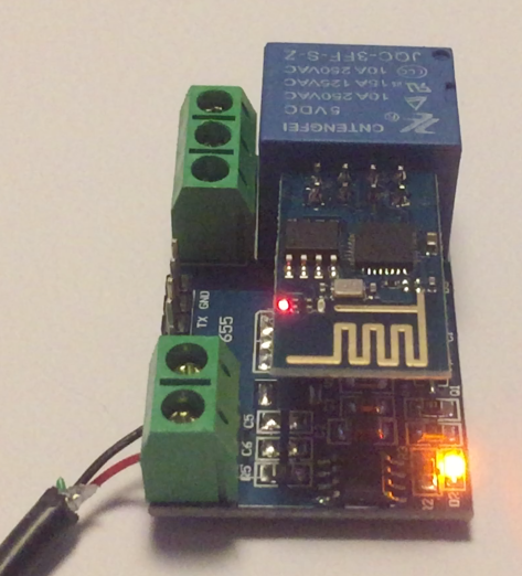
This is a HW-655 relay board designed to work with an ESP-01, the nifty tiny embedded WiFi device. It appears to be a clone of a China LC Technology ESP8266 5V WiFi relay module. I found some documentation here and some more details of a similar product from the same vendor here. I also found warnings that some clones did not have programmed STM8 micro controllers so they don’t work.

The missing element in trying to make this device work was the concept that you control the relay by transmitting serial characters from the ESP-01 rather than controlling an OUTPUT pin. There is a STM8 micro controller on the board. Why do this? I’m not sure but it does leave a couple of IO pins you can solder to. One theory is it ensures the relay doesn’t close without something quite deliberate happening in the ESP-01 which could prevent the ESP-01 crashing and leaving your controlled device powered.

The magic string is four bytes long.

A0 01 01 A2 causes the relay to CLOSE.

A0 01 00 A1 causes it to OPEN.

It’s probably a good idea to flush out any crud in the serial port before you send the string. I have noticed that A0 01 A0 01 01 A2 doesn’t cause the relay to CLOSE.

I wanted to test my relay module to see if it was programmed since it was obviously a clone. I couldn’t enter the four byte sequences in my terminal emulator so I wrote a bit of Perl on my Mac:

$| = 1;
printf("Close");
sleep 1;
printf(chr(0xa0) . chr(0x01) . chr(0x01) . chr(0xa2) ); # close
sleep 1;
printf("Open");
sleep 1;
printf(chr(0xa0) . chr(0x01) . chr(0x00) . chr(0xa1) ); # open
sleep 1;

And ran it like this:

perl < relay-close.pl > /dev/cu.usbserial-A703EA9U

While monitoring the serial being sent like this:

cat /dev/cu.usbserial-A703EA9U | hexdump
0000000 43 6c 6f 73 65 a0 01 01 a2 4f 70 65 6e a0 01 00
0000010 a1 43 6c 6f 73 65 a0 01 01 a2 4f 70 65 6e a0 01

And it worked! (Actually the codes I found online were Open: A0 01 01 A2 and Close: A0 01 00 A1 which are backwards!)

The ESP-01 has an ESP8266 system on chip and some flash. It is also Arduino compatible so you can write C++ code that will execute directly on the device. The next problem is 00 is NULL and strings are terminated with a NULL in C languages so you have apply a bit of effort like:

void setup() {
  Serial.begin(9600);
}

void loop() {
 Serial.write("\xa0\x01\x01\xa2"); // CLOSE RELAY
 delay(1000);
 Serial.write("\xa0\x01"); // OPEN RELAY
 Serial.write(0x00); // null terminates a string so it has to be sent on its own
 Serial.write(0xa1);
 delay(1000);
}

I compiled it for a board type of ESP8266 and uploaded it via my handy little ESP-01 programmer.

ESP-01 programmer - 1

Then plugged the ESP-01 into the HW-655, applied power and the relay will happily turn on and off every second forever.

ESP01 with relay

The ESP-01 is quite clever and can be loaded with some off the shelf firmware that does WiFi and can listen for a TCP connection so you could open a socket and send the four byte sequences from a machine on the same network. If you do some digging you will find some projects using some of Espressif’s IoT tools that let you control these devices from your mobile phone.

Note that there are two versions of the ESP-01. If you’re blowing $3 of your hard earned cash on one or five you should probably buy ESP-01S modules with 1MB of flash rather than the ESP-01 with only 512K of flash. You need the bigger memory for Version 1.5 of the AT “modem” firmware which can remember WiFi and TCP settings.

Other differences between ESP-01 and ESP-01S found online:

– blue PCB vs black
– 512kB flash vs 1MB
– Red power LED vs -No- power LED
– Blue LED on GPIO1 (TX) vs GPIO2 (and low = on)

The difference in LED may cause confusing when using BUILTIN_LED in the Ardunio IDE because the IDE expects the LED on GPIO1 (TX) and it’s inverted so OFF is lit and ON is dark.